|
|
| Installing stainless steel replacement fuel lines |
INSTALLING STAINLESS STEEL REPLACEMENT FUEL LINES
By Clay Perrine
The Porsche 914 has many qualities that make it attractive. Its handling, the ability to be converted to more powerful engines, etc.
But it also has its drawbacks. One of the more serious drawbacks is the fact that Porsche, in an effort to save money, used plastic fuel line inside the body and engine compartment.
After 30 years of neglect, the lines have hardened and become brittle. This can lead to an engine fire. I have experienced this firsthand.
The pain of standing on the side of the road watching your beloved Porsche burn is something that cannot be described.
To replace the fuel lines, you must first start by removing a lot of things in the car.
Fortunately for me, I am in the process of converting my 1973 914 to a six, so the engine and most of the parts that I would normally remove are already out.
Start by pulling the fuel tank. Then remove all the hoses below it. Then pull out the driver’s seat, the center console (if equipped), the floorboard, the “package tray” between the seats, and the metal covers at both the front and back of the tunnel.
It is also MUCH easier if you remove the engine and transmission.
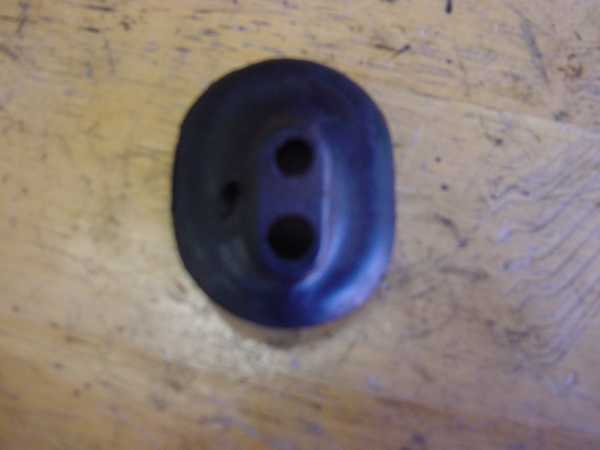
Once you have these parts removed, remove the plastic fuel lines from the tunnel. Save the rubber block that the lines pass through under the fuel tank.
Now you need the fuel lines. I chose stainless steel tubing because it never rusts. You can use mild steel tubing also.
Buy two 16 ft sticks of 7/16 stainless steel tubing, one 3 foot piece of 3.8 stainless tubing, 7/16 and 3/8 fuel injection hose, 7/16 and 3/8 fuel injection hose clamps, padded tubing clamps, self tapping sheet metal screws, and some fine sandpaper.
The specialty tools needed are a tubing cutter, a tubing bender, and a tap and die kit.
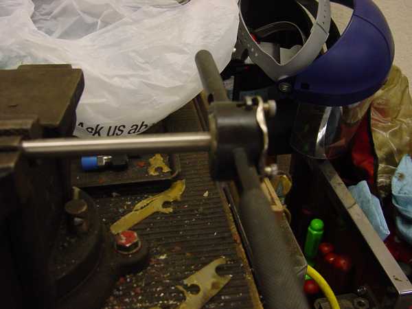
Start off by using a die to thread one end of both of the 16 ft sticks of stainless steel tubing. Use a 10mm die.
7/16 is slightly smaller than 10mm, so the die will only cut vary shallow threads in the tubing. Sand down the threads with the sandpaper to remove any burrs.
The threads will prevent the fuel line from sliding off the tube from fuel pressure.
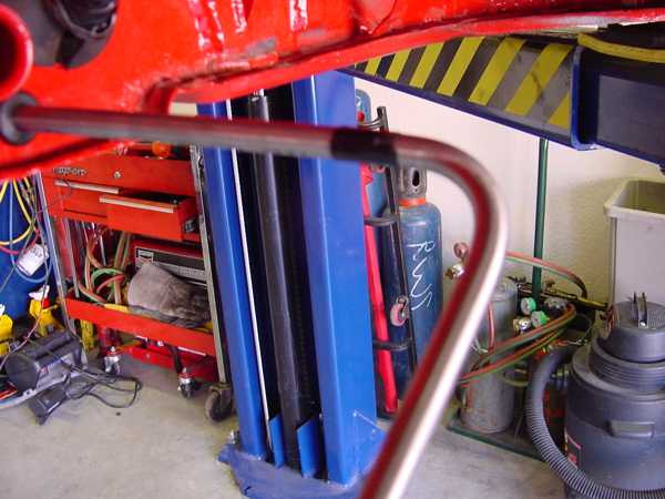
Next insert rubber grommets into the fuel line holes in the firewall.
This will protect the fuel lines from vibration. Spray the threaded end of one of the 16ft sticks of tubing with a lubricant, and insert it into the right hand grommet, being very careful not to get caught up it the wiring harness that lies just inside the firewall.
Push it all the way forward until it hits the front bulkhead. Because of the angle of the holes in the firewall, the line will probably end up by the throttle bell crank on the pedal box.
Have a helper pull the line back until you can push it over and route it into the hole at the front of the tunnel. You should see the line come through the hole below the fuel tank.
Back in the engine compartment, measure 4 inches from the firewall, and put a loop of tape around the tube.
This is the location for the first bend in the tubing. Pull the line until the tape is about 8 to 10 inches from the firewall.
Take the tubing bender and bend the tubing at the tape until it is bent about 110 degrees.
We can’t bend it exactly 90 degrees because d the radius of the bend won’t allow the tube to sit flush against the firewall if it’s bent 90 degrees.
Measure 5 inches from the bend and make a 20 degree bend to bring the tube back parallel with the firewall.
Slowly work the line with the tubing bender until it clears the body work under the battery tray and can come up the factory rear hole for the fuel line.
If you have a 914 /4, you will have an extra brace for the motor mounts to work around.
Once you have finished bending the line to the correct shape, use the die to thread the engine compartment end of the line.
Push the line forward until it is routed through the hole under the tank again, and place a rag under the line.
Then take a rubber mallet and hit the fuel line to push it farther up into the tunnel. You should just see the curve start at the grommet.
The second line is almost like the first, but it requires an additional bend to go over the first line.
After the 110 degree bend, make a slight 10 degree bend to bring it over the first line, then the 20 degree bend to bring it parallel with the firewall.
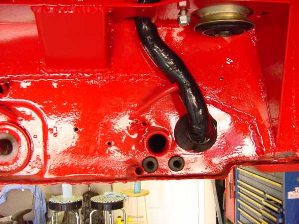
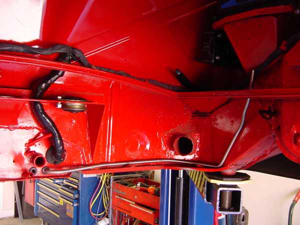
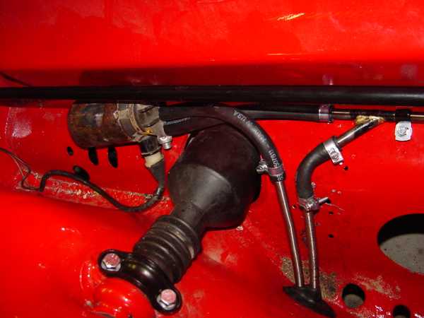
Insert the padded tubing clamps at regular intervals to hold the line securely in place. This is essential if you use stainless line.
It will work harden and crack if not properly clamped down. The picture below does not have enough clamps.
Install the factory rubber grommets on the lines where they come through the engine shelf.
In the fuel tank hole, bend the fuel lines up slightly, until they curve upward and can be held free of the rise in the sheet metal that covers the steering rack.
Lubricate the end of the lines, and install the grommet over the lines and into the hole between the passenger compartment and the tank well.
If you have a 74 or older car, the grommet will have 2 different sized holes in it.
You will need to make the smaller of the 2 holes the same size as the larger one.
Installing this grommet is very difficult due to its location, and the inflexibility of the steel lines.
Take a section of the 7/16 tubing that you cut off in the engine compartment, and thread the end.
Then bend it so that it will put one connection down at the right front corner of the bottom of the tank well.
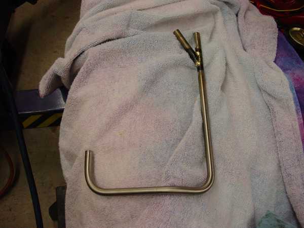
I chose to make a Y fitting in my line by braising on a second piece of tubing, and then drilling down it until it was open to the other tube.
I pressure tested it by looping the 2 ends of the fitting together with a piece of fuel line, and immersing it in a bucket of water.
Then I blew compressed air in it at 100 psi and checked for bubbles.
This line is the return line. If you don’t want to braise up the line like I did, you can buy a t- fitting for the return line.
If you have a 75 or 76 914, you don’t need the Y fitting.
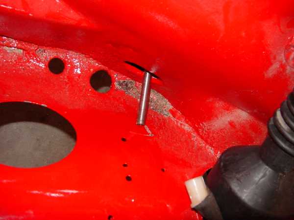
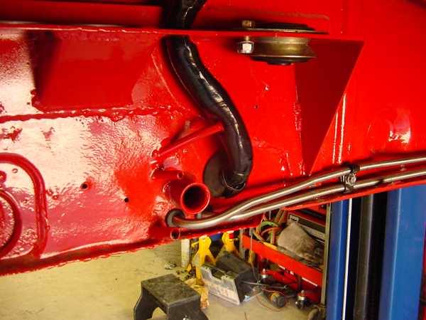
Here is the line installed in the tank well.
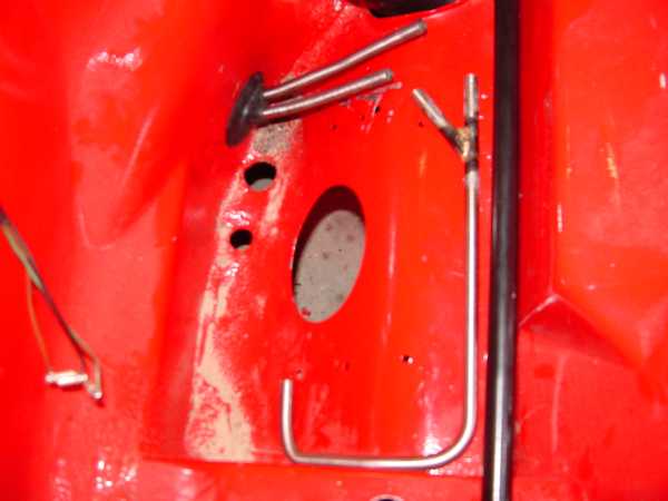
Notice that the line ends up at the front of the tank well, close to the hole. It also follows the contour of the sheet metal.
Next we bend a 3/8 line to act as the suction line from the tank to the pump. It should run along the right hand wall of the tank well, and come up and attach to the front trunk wall support, following the contour of the sheet metal.
The slight bend in the end of the line at the fuel pump brings it away from the bulkhead so that the fuel hose to connect to the pump can be easily attached.
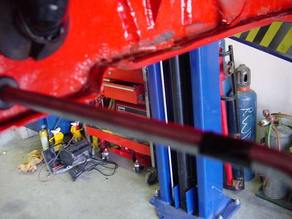
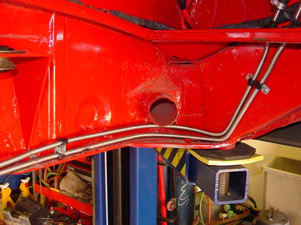
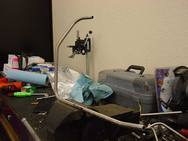
Here is a picture of everything but the suction line installed under the tank. I have not finished mounting the pump in this picture.
Again, make sure that you tie down the lines under the tank with clamps to prevent work hardening due to vibration.
|
|