|
|
|
Porsche, and the Porsche crest are registered trademarks of Dr. Ing. h.c. F. Porsche AG.
This site is not affiliated with Porsche in any way. Its only purpose is to provide an online forum for car enthusiasts. All other trademarks are property of their respective owners. |
|
|

  |

| pgollender |
 Apr 27 2025, 03:31 PM Apr 27 2025, 03:31 PM
Post
#1
|
|
Member  Group: Members Posts: 198 Joined: 5-July 11 From: Sacramento Member No.: 13,281 Region Association: Northern California |
I am trying to expand off Dave Darling’s old posts on the Pelican and from info archived from Brad Anders pages. Many thanks to Paul Wiles who supplied me with a few dead AAR’s to experiment with.
The mechanical rebuilding process has been explained in detail including a nice piece by Ian Karr. The problem with many of our AAR (Auxillary air valve regulators) is that the 12volt lead has broken off or the NiChrome heating element has broken off or burnt out. Depending on whether your valve is stuck open or frozen shut will affect either the warmup process or performance of your 914 after it has reached operating temperature. This is assuming that your cold start valve is also functioning properly. The insulated 12volt lead passes through the bottom of the AAR then through a thin pressed fire-retardant material and is riveted to a copper pin on the inside of the ceramic heat-sink. From the pin connection, a 13 ohm wound niChrome heating element (resistor) exits counter-clockwise to a grounding copper rivet that grounds to the bottom of the AAR. The ceramic heat sink is also riveted centrally to the bottom of the AAR. In the original design the wound NiChrome wire is epoxied to a small round kerf in two places. It is 99% impossible to remove the epoxy/wire without either destroying the wire or the round kerf mounting surface. I have included a few pictures to help look at the structures. Per Dave Darlings Pelican notes I ordered some ceramic “5 watt bathtub resistors” and will connect them in series to obtain 13 ohms. It’s been along time since I used Ohm’s law so I’m not 100% sure if I am doing this right. Anyway you have to remove the ceramic tub to have enough clearance for the metallic spring to fit. I haven’t completed the project yet but wanted to post the project so far. I still need to secure the resistors in place and find a suitable 12volt wire insulator to pass through the narrow channel and then be able to ground it to the AAR chassis properly. 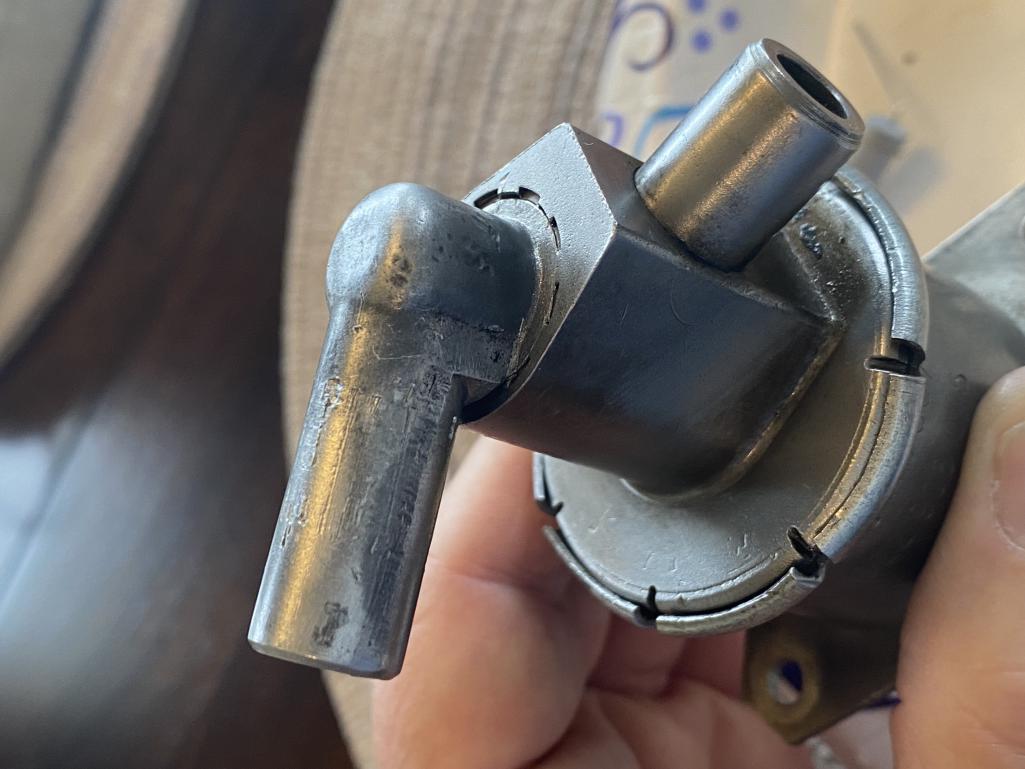 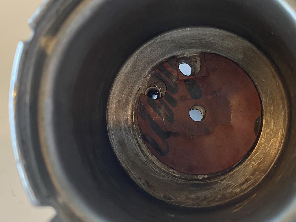 |
   |

 
|
| pgollender |
Apr 27 2025, 03:37 PM
Post
#2
|
|
Member Group: Members Posts: 198 Joined: 5-July 11 From: Sacramento Member No.: 13,281 Region Association: Northern California |
QUOTE(pgollender @ Apr 27 2025, 02:31 PM)  I am trying to expand off Dave Darling’s old posts on the Pelican and from info archived from Brad Anders pages. Many thanks to Paul Wiles who supplied me with a few dead AAR’s to experiment with. The mechanical rebuilding process has been explained in detail including a nice piece by Ian Karr. The problem with many of our AAR (Auxillary air valve regulators) is that the 12volt lead has broken off or the NiChrome heating element has broken off or burnt out. Depending on whether your valve is stuck open or frozen shut will affect either the warmup process or performance of your 914 after it has reached operating temperature. This is assuming that your cold start valve is also functioning properly. The insulated 12volt lead passes through the bottom of the AAR then through a thin pressed fire-retardant material and is riveted to a copper pin on the inside of the ceramic heat-sink. From the pin connection, a 13 ohm wound niChrome heating element (resistor) exits counter-clockwise to a grounding copper rivet that grounds to the bottom of the AAR. The ceramic heat sink is also riveted centrally to the bottom of the AAR. In the original design the wound NiChrome wire is epoxied to a small round kerf in two places. It is 99% impossible to remove the epoxy/wire without either destroying the wire or the round kerf mounting surface. I have included a few pictures to help look at the structures. Per Dave Darlings Pelican notes I ordered some ceramic “5 watt bathtub resistors” and will connect them in series to obtain 13 ohms. It’s been along time since I used Ohm’s law so I’m not 100% sure if I am doing this right. Anyway you have to remove the ceramic tub to have enough clearance for the metallic spring to fit. I haven’t completed the project yet but wanted to post the project so far. I still need to secure the resistors in place and find a suitable 12volt wire insulator to pass through the narrow channel and then be able to ground it to the AAR chassis properly. Attached thumbnail(s) 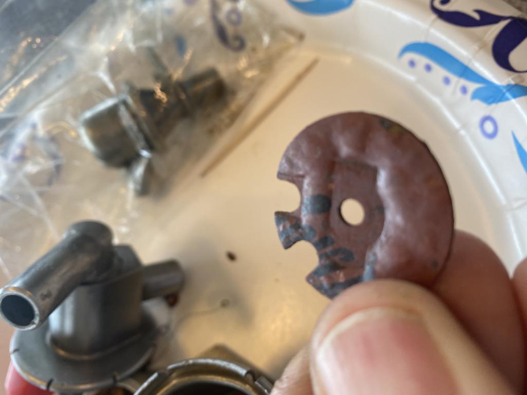 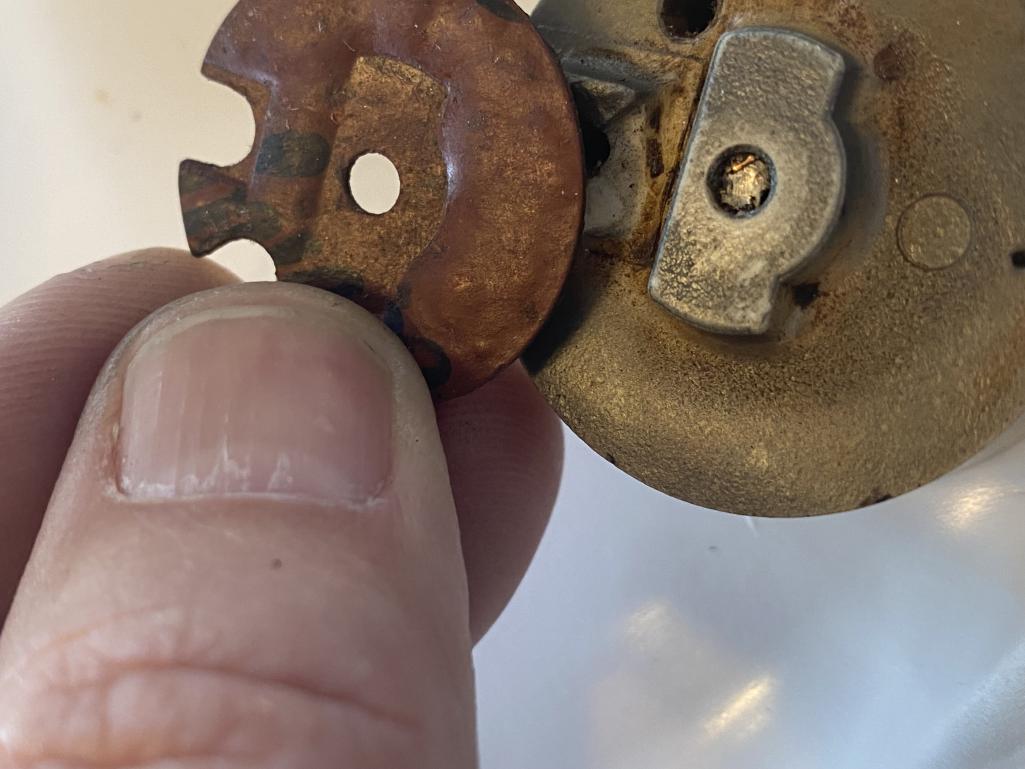
|
|
|
|
| pgollender |
Apr 27 2025, 03:39 PM
Post
#3
|
|
Member Group: Members Posts: 198 Joined: 5-July 11 From: Sacramento Member No.: 13,281 Region Association: Northern California |
QUOTE(pgollender @ Apr 27 2025, 02:37 PM) QUOTE(pgollender @ Apr 27 2025, 02:31 PM) I am trying to expand off Dave Darling’s old posts on the Pelican and from info archived from Brad Anders pages. Many thanks to Paul Wiles who supplied me with a few dead AAR’s to experiment with. The mechanical rebuilding process has been explained in detail including a nice piece by Ian Karr. The problem with many of our AAR (Auxillary air valve regulators) is that the 12volt lead has broken off or the NiChrome heating element has broken off or burnt out. Depending on whether your valve is stuck open or frozen shut will affect either the warmup process or performance of your 914 after it has reached operating temperature. This is assuming that your cold start valve is also functioning properly. The insulated 12volt lead passes through the bottom of the AAR then through a thin pressed fire-retardant material and is riveted to a copper pin on the inside of the ceramic heat-sink. From the pin connection, a 13 ohm wound niChrome heating element (resistor) exits counter-clockwise to a grounding copper rivet that grounds to the bottom of the AAR. The ceramic heat sink is also riveted centrally to the bottom of the AAR. In the original design the wound NiChrome wire is epoxied to a small round kerf in two places. It is 99% impossible to remove the epoxy/wire without either destroying the wire or the round kerf mounting surface. I have included a few pictures to help look at the structures. Per Dave Darlings Pelican notes I ordered some ceramic “5 watt bathtub resistors” and will connect them in series to obtain 13 ohms. It’s been along time since I used Ohm’s law so I’m not 100% sure if I am doing this right. Anyway you have to remove the ceramic tub to have enough clearance for the metallic spring to fit. I haven’t completed the project yet but wanted to post the project so far. I still need to secure the resistors in place and find a suitable 12volt wire insulator to pass through the narrow channel and then be able to ground it to the AAR chassis properly. Attached thumbnail(s) 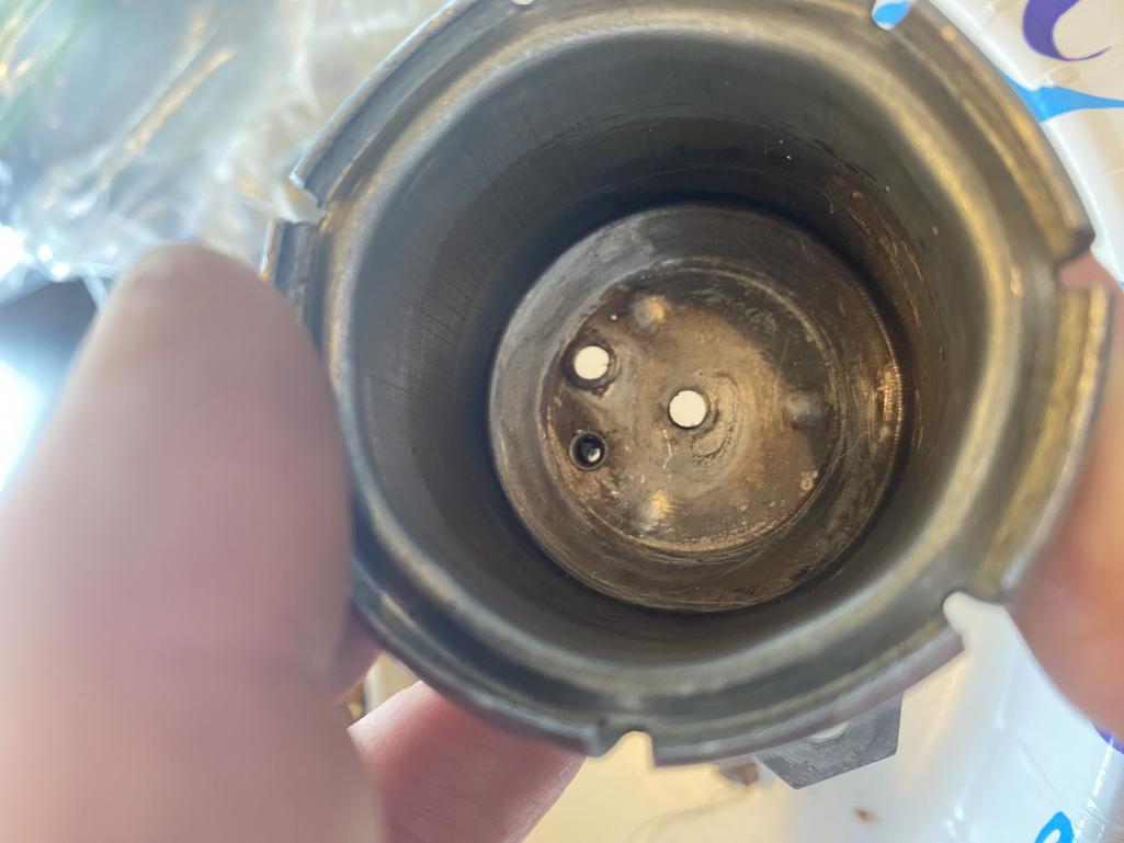 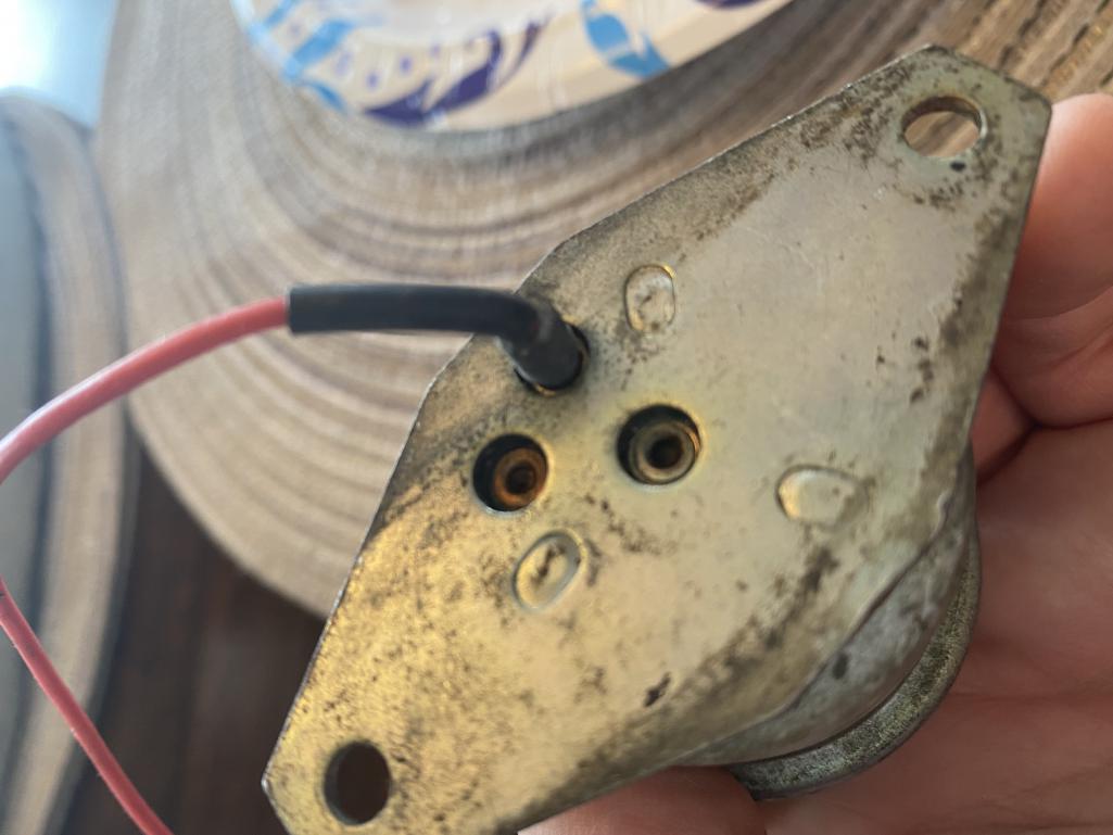
|
|
|
|
| pgollender |
Apr 27 2025, 03:40 PM
Post
#4
|
|
Member Group: Members Posts: 198 Joined: 5-July 11 From: Sacramento Member No.: 13,281 Region Association: Northern California |
QUOTE(pgollender @ Apr 27 2025, 02:39 PM) QUOTE(pgollender @ Apr 27 2025, 02:37 PM) QUOTE(pgollender @ Apr 27 2025, 02:31 PM) I am trying to expand off Dave Darling’s old posts on the Pelican and from info archived from Brad Anders pages. Many thanks to Paul Wiles who supplied me with a few dead AAR’s to experiment with. The mechanical rebuilding process has been explained in detail including a nice piece by Ian Karr. The problem with many of our AAR (Auxillary air valve regulators) is that the 12volt lead has broken off or the NiChrome heating element has broken off or burnt out. Depending on whether your valve is stuck open or frozen shut will affect either the warmup process or performance of your 914 after it has reached operating temperature. This is assuming that your cold start valve is also functioning properly. The insulated 12volt lead passes through the bottom of the AAR then through a thin pressed fire-retardant material and is riveted to a copper pin on the inside of the ceramic heat-sink. From the pin connection, a 13 ohm wound niChrome heating element (resistor) exits counter-clockwise to a grounding copper rivet that grounds to the bottom of the AAR. The ceramic heat sink is also riveted centrally to the bottom of the AAR. In the original design the wound NiChrome wire is epoxied to a small round kerf in two places. It is 99% impossible to remove the epoxy/wire without either destroying the wire or the round kerf mounting surface. I have included a few pictures to help look at the structures. Per Dave Darlings Pelican notes I ordered some ceramic “5 watt bathtub resistors” and will connect them in series to obtain 13 ohms. It’s been along time since I used Ohm’s law so I’m not 100% sure if I am doing this right. Anyway you have to remove the ceramic tub to have enough clearance for the metallic spring to fit. I haven’t completed the project yet but wanted to post the project so far. I still need to secure the resistors in place and find a suitable 12volt wire insulator to pass through the narrow channel and then be able to ground it to the AAR chassis properly. Attached thumbnail(s)  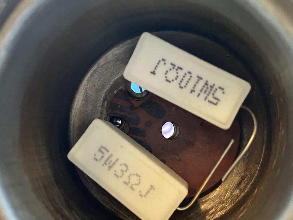
|
|
|
|
| pgollender |
Apr 27 2025, 03:44 PM
Post
#5
|
|
Member Group: Members Posts: 198 Joined: 5-July 11 From: Sacramento Member No.: 13,281 Region Association: Northern California |
QUOTE(pgollender @ Apr 27 2025, 02:40 PM) QUOTE(pgollender @ Apr 27 2025, 02:39 PM) QUOTE(pgollender @ Apr 27 2025, 02:37 PM) QUOTE(pgollender @ Apr 27 2025, 02:31 PM) I am trying to expand off Dave Darling’s old posts on the Pelican and from info archived from Brad Anders pages. Many thanks to Paul Wiles who supplied me with a few dead AAR’s to experiment with. The mechanical rebuilding process has been explained in detail including a nice piece by Ian Karr. The problem with many of our AAR (Auxillary air valve regulators) is that the 12volt lead has broken off or the NiChrome heating element has broken off or burnt out. Depending on whether your valve is stuck open or frozen shut will affect either the warmup process or performance of your 914 after it has reached operating temperature. This is assuming that your cold start valve is also functioning properly. The insulated 12volt lead passes through the bottom of the AAR then through a thin pressed fire-retardant material and is riveted to a copper pin on the inside of the ceramic heat-sink. From the pin connection, a 13 ohm wound niChrome heating element (resistor) exits counter-clockwise to a grounding copper rivet that grounds to the bottom of the AAR. The ceramic heat sink is also riveted centrally to the bottom of the AAR. In the original design the wound NiChrome wire is epoxied to a small round kerf in two places. It is 99% impossible to remove the epoxy/wire without either destroying the wire or the round kerf mounting surface. I have included a few pictures to help look at the structures. Per Dave Darlings Pelican notes I ordered some ceramic “5 watt bathtub resistors” and will connect them in series to obtain 13 ohms. It’s been along time since I used Ohm’s law so I’m not 100% sure if I am doing this right. Anyway you have to remove the ceramic tub to have enough clearance for the metallic spring to fit. I haven’t completed the project yet but wanted to post the project so far. I still need to secure the resistors in place and find a suitable 12volt wire insulator to pass through the narrow channel and then be able to ground it to the AAR chassis properly. Attached thumbnail(s) 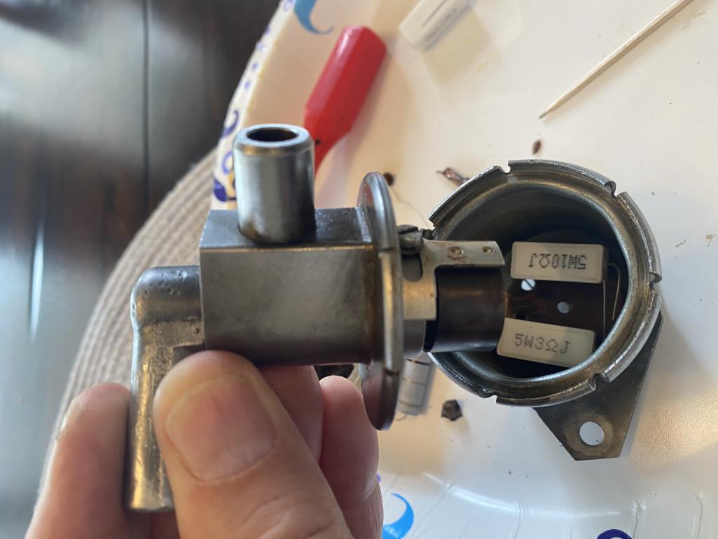
|
|
|
|
| emerygt350 |
Apr 27 2025, 04:03 PM
Post
#6
|
|
Advanced Member Group: Members Posts: 2,883 Joined: 20-July 21 From: Upstate, NY Member No.: 25,740 Region Association: North East States |
Very interesting! Best of luck! I was thinking about attacking the problem from scratch using a electromechanical vacuum switch but that won't look stock.
|
 |
|
| 914sgofast2 |
Apr 27 2025, 11:17 PM
Post
#7
|
|
Senior Member Group: Members Posts: 717 Joined: 10-May 13 From: El Dorado Hills, CA Member No.: 15,855 Region Association: None |
So is it your plan to replace the heating element with those 2 resistors in order to generate the heat needed to make the spring expand and contract as it heats and cools? That might be easier than making a new heating element wire and riveting it to the AAR’s ceramic base component.
|
|
|
|
| Superhawk996 |
Apr 28 2025, 07:48 AM
Post
#8
|
|
914 Guru Group: Members Posts: 7,028 Joined: 25-August 18 From: Woods of N. Idaho Member No.: 22,428 Region Association: Galt's Gulch |
QUOTE(pgollender @ Apr 27 2025, 05:31 PM) I ordered some ceramic “5 watt bathtub resistors” and will connect them in series to obtain 13 ohms. It’s been along time since I used Ohm’s law so I’m not 100% sure if I am doing this right. You are forgetting the power side of ohms law. I’m going to use 13v as nominal voltage to keep the math simple Current = voltage / resistance = 13/13 =1 amp Power = current ^2 x resistance = 1x1x13 =13 watts total. You only have 10 watts (max) with your two 5 watt resistors. The bigger problem is that power formula also applies for each resistor individually. So resistor #1 - 10 ohms Power = 1x1x10 =10 watts. Problem is your resistor is only 5 watts and that assumes it’s in free air and able to cool via air. Your 5 watts total resistor is eventually going to burn out trying to dissipate 10watts inside an enclosed canister. The AAR is continuously powered so that only makes matters worse with a 100% duty cycle. Resistor #2 - 3 ohms Power = 1x1x3 =3 watts This resistor would be ok in theory but again packing it along side the 10W coming off resistor #1 in an enclosed space is going to overheat it too. You can redo the math at 12v nominal but you’ll see that resistor #1 is still at 8.5 watts. If you could squeeze three 5 ohm 5 watt resistors in there the math works in theory but I suspect that it will still burn out pretty quickly due to poor heat transfer from resistors to the AAR housing and then to air. Hard to say for sure how long it might live but that would be the way to try. |
|
|
|
| Spoke |
Apr 28 2025, 11:35 AM
Post
#9
|
|
Jerry Group: Members Posts: 7,158 Joined: 29-October 04 From: Allentown, PA Member No.: 3,031 Region Association: None |
Interesting way to produce heat using power resistors. As @Superhawk996 mentioned, you want to use equal value resistors and probably use 3 resistors.
One other thing to keep in mind is all resistors have derating factors based on ambient temperatures. Below are temperature curves for this 7W resistor: ER5847RJT Link: TE ER5847RJT RES 47 OHM 5% 7W AXIAL The resistor in the link is 47 ohms. There are 2 ways to connect resistors to get a different value. In series the resistances multiply R * Num; in parallel the resistances divide R / Num where Num is the number of equal value resistors. I chose 47 ohm since I thought it would be easier to just make 2 connections (power, GND) inside the can if in parallel versus 4 if in series. The three 47 ohm resistors will equate to 15.5 ohms and will burn 12.5W. Each resistor burning 4.2W. At 4W the surface temp of the resistors is about 200C from the right curve for the ER58 series. The derating curve says the 7W resistor @ 200C can burn about 4W so should be ok. You should test this on the bench and see how long it takes for the AAR to open. The resistance can be adjusted up if too quick. If too slow you'd need to find a new resistor. 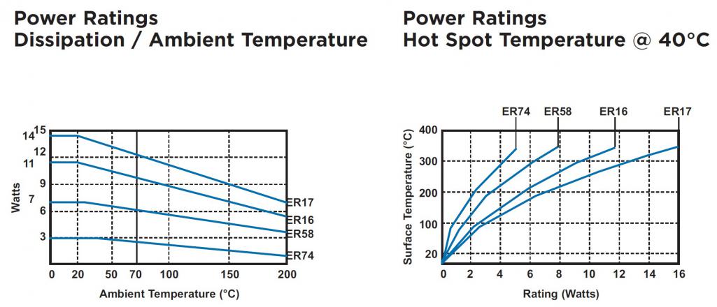 |
|
|
|
|
1 User(s) are reading this topic (1 Guests and 0 Anonymous Users)
0 Members:

|
Lo-Fi Version | Time is now: 9th May 2025 - 02:50 PM |
Invision Power Board
v9.1.4 © 2025 IPS, Inc.