|
|
|
Porsche, and the Porsche crest are registered trademarks of Dr. Ing. h.c. F. Porsche AG.
This site is not affiliated with Porsche in any way. Its only purpose is to provide an online forum for car enthusiasts. All other trademarks are property of their respective owners. |
|
|

  |

| sdoolin |
 Feb 7 2025, 04:42 PM Feb 7 2025, 04:42 PM
Post
#1
|
|
Member  Group: Members Posts: 414 Joined: 1-May 14 From: LouKY Member No.: 17,299 Region Association: None |
Rebuilding(ish) my 2056. On my first build I was able to achieve a compression ratio of very nearly 9.0:1. With this build, I am having to add .020 spacers below the jugs to get any measurable deck height in the jugs. I am calculating a compression ratio of 8.6:1.
Will I notice the loss in compression ratio? |
   |

 
|
| technicalninja |
Feb 7 2025, 05:38 PM
Post
#2
|
|
Advanced Member Group: Members Posts: 2,456 Joined: 31-January 23 From: Granbury Texas Member No.: 27,135 Region Association: Southwest Region |
You need AT LEAST .036 with cast and .040+ with forged pistons.
This is piston top to cylinder top (deck height). I am assuming you are not using fire rings (shims on the head side of things). Any less and you risk piston to head contact. This is fatal! The compression difference will be tiny. Now, for proper quench action you want "as tight as possible without P-H contact". The deck height MUST be measured in line with the pin. The more piston to wall clearance you have the more deck clearance you need. Run tight cast clearances and you can go tighter than .040. Run loose forged clearance and you will need more. Larger bores need more as well. For performance engines I want to be ALWAYS less than .045... |
|
|
|
| sdoolin |
Feb 7 2025, 06:02 PM
Post
#3
|
|
Member Group: Members Posts: 414 Joined: 1-May 14 From: LouKY Member No.: 17,299 Region Association: None |
Measured deck height in the jug, with an .020 spacer below the jug, is just at .6mm. Add the 1mm in the HAM heads (do NOT start a separate conversation about this) and you get 1.6mm. Which is a lot. Without the .020 spacer the pistons rise above the top of the jugs. Which scares me.
No fire rings in the heads. |
|
|
|
| Superhawk996 |
Feb 7 2025, 06:21 PM
Post
#4
|
|
914 Guru Group: Members Posts: 6,813 Joined: 25-August 18 From: Woods of N. Idaho Member No.: 22,428 Region Association: Galt's Gulch |
Sounds like you are playing with fire.
Without seeing how you are measuring or the heads I wouldn’t start an engine with .6mm of deck height. |
|
|
|
| technicalninja |
Feb 7 2025, 06:57 PM
Post
#5
|
|
Advanced Member Group: Members Posts: 2,456 Joined: 31-January 23 From: Granbury Texas Member No.: 27,135 Region Association: Southwest Region |
QUOTE(sdoolin @ Feb 7 2025, 06:02 PM)  Measured deck height in the jug, with an .020 spacer below the jug, is just at .6mm. Add the 1mm in the HAM heads (do NOT start a separate conversation about this) and you get 1.6mm. Which is a lot. Without the .020 spacer the pistons rise above the top of the jugs. Which scares me. No fire rings in the heads. Please post a picture of the combustion chamber of those HAM heads. You're either running .024" deck height OR .064" At .064" you are leaving 5-10% of the obtainable performance on the table AND the engine will be MORE prone to detonation. You're building a turd. (IMG:style_emoticons/default/stromberg.gif) At .024" it will most likely disintegrate directly after start up... (IMG:style_emoticons/default/blowup.gif) And if you are not open to the assistance of others regarding everything about this why in the world did you post at all? If I had $$$ HAM heads and I was unsure of what I was doing I'd want as much feedback as possible. Both me and the Hawk are serious engine builders, we both know what we are doing, sometimes we disagree but it is ALWAYS about minor things. If you DON"T want help... (IMG:style_emoticons/default/ninja.gif) |
|
|
|
| sdoolin |
Feb 7 2025, 07:26 PM
Post
#6
|
|
Member Group: Members Posts: 414 Joined: 1-May 14 From: LouKY Member No.: 17,299 Region Association: None |
QUOTE(Superhawk996 @ Feb 7 2025, 07:21 PM) Sounds like you are playing with fire. Without seeing how you are measuring or the heads I wouldn’t start an engine with .6mm of deck height. Total deck height is 1.6mm. I am very sure of this. |
|
|
|
| sdoolin |
Feb 7 2025, 07:27 PM
Post
#7
|
|
Member Group: Members Posts: 414 Joined: 1-May 14 From: LouKY Member No.: 17,299 Region Association: None |
Yep, I don't want this help. Y'all go build your own shit.
|
|
|
|
| sdoolin |
Feb 7 2025, 07:29 PM
Post
#8
|
|
Member Group: Members Posts: 414 Joined: 1-May 14 From: LouKY Member No.: 17,299 Region Association: None |
I especially like the turd bit.
|
|
|
|
| Superhawk996 |
Feb 7 2025, 07:30 PM
Post
#9
|
|
914 Guru Group: Members Posts: 6,813 Joined: 25-August 18 From: Woods of N. Idaho Member No.: 22,428 Region Association: Galt's Gulch |
QUOTE(sdoolin @ Feb 7 2025, 09:26 PM) QUOTE(Superhawk996 @ Feb 7 2025, 07:21 PM) Sounds like you are playing with fire. Without seeing how you are measuring or the heads I wouldn’t start an engine with .6mm of deck height. Total deck height is 1.6mm. I am very sure of this. By definition, deck height has nothing to do with the head. 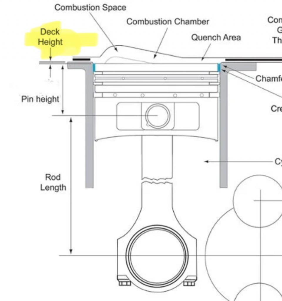 |
|
|
|
| sdoolin |
Feb 7 2025, 07:33 PM
Post
#10
|
|
Member Group: Members Posts: 414 Joined: 1-May 14 From: LouKY Member No.: 17,299 Region Association: None |
Superhawk thank you for your reasonable response. I add the 1mm to overall deck height at the instruction of Len Hoffman at HAMM. I trust him. I really do.
|
|
|
|
| Superhawk996 |
Feb 7 2025, 07:44 PM
Post
#11
|
|
914 Guru Group: Members Posts: 6,813 Joined: 25-August 18 From: Woods of N. Idaho Member No.: 22,428 Region Association: Galt's Gulch |
QUOTE(sdoolin @ Feb 7 2025, 09:33 PM) Superhawk thank you for your reasonable response. I add the 1mm to overall deck height at the instruction of Len Hoffman at HAMM. I trust him. I really do. Len is an expert no doubt. But, is it possible you misunderstood? What was his recommendation for deck height not including his head? Unless you can guarantee the heads have been machined to have a slightly larger OD of the sealing surface than the OD of your cylinders you have a potential for contact between the piston and the head. I don’t see how you can be running .6mm deck clearance and still only netting a 8.6:1 CR. Proceed at your own risk. At a bare minimum I’d be triple checking the fit with Prussian Blue and then double checking the piston top with clay. Tread carefully. |
|
|
|
| Jack Standz |
Feb 8 2025, 03:05 AM
Post
#12
|
|
Member Group: Members Posts: 474 Joined: 15-November 19 From: Happy Place (& surrounding area) Member No.: 23,644 Region Association: None |
QUOTE(sdoolin @ Feb 8 2025, 05:42 AM) Rebuilding(ish) my 2056. On my first build I was able to achieve a compression ratio of very nearly 9.0:1. With this build, I am having to add .020 spacers below the jugs to get any measurable deck height in the jugs. I am calculating a compression ratio of 8.6:1. Will I notice the loss in compression ratio? To answer your original question, probably not from just a small change in the CR. That's with all things being equal. But, if your actual deck height is too large (and before it was "spot on"), and the quench is negatively affected, it will affect the motor's output. Our 2056 has a CR about 8.5 or 8.6 (if I remember correctly, I have some notes somewhere). Nice motor & no complaints here. It turned out to be just what we wanted for a street motor in our '74. LN Engineering heads are very very good. Would like a set or two for some upcoming projects. Their RS+ or LE200 heads are expensive too. When the motor is built according to Len's instructions, you will notice a huge difference in performance with these heads compared to standard heads or heads from mere mortals. Best wishes for the rebuild. |
 |
|
| sdoolin |
Feb 8 2025, 07:35 AM
Post
#13
|
|
Member Group: Members Posts: 414 Joined: 1-May 14 From: LouKY Member No.: 17,299 Region Association: None |
QUOTE(Jack Standz @ Feb 8 2025, 04:05 AM) QUOTE(sdoolin @ Feb 8 2025, 05:42 AM) Rebuilding(ish) my 2056. On my first build I was able to achieve a compression ratio of very nearly 9.0:1. With this build, I am having to add .020 spacers below the jugs to get any measurable deck height in the jugs. I am calculating a compression ratio of 8.6:1. Will I notice the loss in compression ratio? To answer your original question, probably not from just a small change in the CR. That's with all things being equal. But, if your actual deck height is too large (and before it was "spot on"), and the quench is negatively affected, it will affect the motor's output. Our 2056 has a CR about 8.5 or 8.6 (if I remember correctly, I have some notes somewhere). Nice motor & no complaints here. It turned out to be just what we wanted for a street motor in our '74. LN Engineering heads are very very good. Would like a set or two for some upcoming projects. Their RS+ or LE200 heads are expensive too. When the motor is built according to Len's instructions, you will notice a huge difference in performance with these heads compared to standard heads or heads from mere mortals. Best wishes for the rebuild. Thank you sir, I appreciate this input. I am re-using a set of HAMM RS+ spec cylinder heads. They have about 4k miles on them and I agree with you about them. This motor ran very very nicely on its first build. |
|
|
|
| sdoolin |
Feb 8 2025, 12:37 PM
Post
#14
|
|
Member Group: Members Posts: 414 Joined: 1-May 14 From: LouKY Member No.: 17,299 Region Association: None |
Bolted things up on one side of the engine today and clayed the heads. I am measuring more than 0.1" between piston and valves. From my last build, this seems safe? I am double and triple checking as I have lost some trust in my own capabilities to do this stuff. Older than I used to be.
This is with a .020" spacer below the jugs. No "gaskets" in the heads. |
|
|
|
| Superhawk996 |
Feb 8 2025, 01:43 PM
Post
#15
|
|
914 Guru Group: Members Posts: 6,813 Joined: 25-August 18 From: Woods of N. Idaho Member No.: 22,428 Region Association: Galt's Gulch |
0.100” clearance to the exhaust valve is starting to push what I’d call reasonable for an aircooled street engine. There are water pumper race engines running less. The fact that you said “more than” rather than an exact number concerns me.
The clearance to intake isn’t as critical. The intake valve chases the piston on the intake stroke. The piston chases the exhaust valve on the exhaust stroke. However, remember that air cooled engines run hot vs water-pumpers so growth of the exhaust valve, piston expansion, and rod stretch at high RPM and valve float at high RPM can be a thing. I’d be checking that clay clearance on all 4 cylinders and making sure I’m making that measurement accurately and not just relying on 1 cylinder to represent all 4. I’m also going to suggest that you should be talking with Len and following his advice for valve to piston clearances if you’re trying to build an engine that is trying to absolutely maximize HP by building to the edges of limits of safety that were built into stock components. Don’t rely exclusively on some internet dope like me. (IMG:style_emoticons/default/laugh.gif) |
|
|
|
| Jack Standz |
Feb 8 2025, 03:04 PM
Post
#16
|
|
Member Group: Members Posts: 474 Joined: 15-November 19 From: Happy Place (& surrounding area) Member No.: 23,644 Region Association: None |
QUOTE(sdoolin @ Feb 9 2025, 01:37 AM) Bolted things up on one side of the engine today and clayed the heads. I am measuring more than 0.1" between piston and valves. From my last build, this seems safe? I am double and triple checking as I have lost some trust in my own capabilities to do this stuff. Older than I used to be. This is with a .020" spacer below the jugs. No "gaskets" in the heads. A lot of this stuff requires carefully designing, measuring and implementing it into your engine build. We can't know what's up with your motor by typing on our keyboards. (IMG:style_emoticons/default/smile.gif) Heck, we don't know what cam you're running and whether it's lift exceeds coil bind in your heads. This is an important, but different issue than either piston to valve clearance or deck height. We also don't know anything about your last build and how it went (or didn't). Yes, double and triple check your measurements. Make sure you rotate the motor through at least 720 degrees (two+ full revolutions). It takes 2 revolutions of the crankshaft to complete one combustion cycle. Depending on your cam, you can have valves hit a piston at a point other than Top Dead Center(TDC). And, of course, clearance between the piston and valve is critical as well as deck height. One, so they don't hit each other. And, also so you have good quench and don't kill power. If you don't trust your own capabilities, finding someone you do trust might be the best way forward. There are good competent engine builders out there. Something to consider. Those heads cost more than $5,000 (with tax & shipping), it'd be a shame to not have them reach their full potential (IMG:style_emoticons/default/driving-girl.gif). |
|
|
|
| sdoolin |
Feb 8 2025, 04:32 PM
Post
#17
|
|
Member Group: Members Posts: 414 Joined: 1-May 14 From: LouKY Member No.: 17,299 Region Association: None |
Thank you both for the thoughtful replies. My original build is here - http://www.914world.com/bbs2/index.php?showtopic=273923.
The cam is a Webcam 9130. I set valve geometry on the first build and cut pushrods to length. That build went very well, and the engine was very strong and reliable for just over 4k miles. It was a lot of fun. Due to my own mistakes after a rebuild to fix oil leaks, I find myself here. The only difference from this build to the original build is the crankshaft (and of course new bearings). Importantly in the first build I had to shave the tops of the jugs to achieve the compression I desired (9.0:1(ish)). Now I am having to use a .020" spacer under that same set of jugs to achieve close to my desired compression ratio. I am trying to build this more on the reliable side than the hyper performance side to answer Hawk's question. And Hawk your not a dope. I agree with measuring everything, repeatedly. So I took Hawk's advice and clayed all 4 cylinders. I am measuring 0.15", 0.15", 0.146", and 0.15" exhaust valve clearance across all 4 cylinders. Intake valve clearance is 0.14", 0.14", 0.102" and, 0.11". I'm going to try to get the intakes all closer to one another. I am comfortable with my deck height measurements (discussed previously). Visually I am not seeing coil bind at the valve springs, but I haven't measured that yet. I was hoping to avoid that, but now feel obligated. I have done it before. But I really agree with the point about not leaving any performance on the table with respect to the cost of these heads. They are the single most expensive automotive parts I have ever purchased (except for the 3.8l pistons & cylinders for my 993). That is not a complaint towards HAMM. |
|
|
|
| Superhawk996 |
Feb 8 2025, 10:28 PM
Post
#18
|
|
914 Guru Group: Members Posts: 6,813 Joined: 25-August 18 From: Woods of N. Idaho Member No.: 22,428 Region Association: Galt's Gulch |
0.140” - 0.150” clearance to exhaust valves is a whole lot more comfortable. That “extra” 0.040” or 1 mm doesn’t seem like much but it’s a lot in engine build world and offsets a lot of thermal growth.
Keep measuring and mocking up as you go. It’s good standard practice to do several mockups before any final assembly. Better safe than sorry. |
|
|
|
| sdoolin |
Feb 9 2025, 05:03 PM
Post
#19
|
|
Member Group: Members Posts: 414 Joined: 1-May 14 From: LouKY Member No.: 17,299 Region Association: None |
Measured valve lift a bunch of times today. Worst case I am losing .036" of lift at the exhaust valves, and .018" of lift at the intake valves. Best case I am achieving slightly greater than advertised lift on this cam (.435). So I am good with it and am not going to bother measuring for new pushrods. The geometry at half lift looks really really good, things are lined up well.
Will proceed with final assembly. I will have questions about oil pressure verification soon. A pic, because pics help everything (and 914 world autorotates my pics for some reason)... 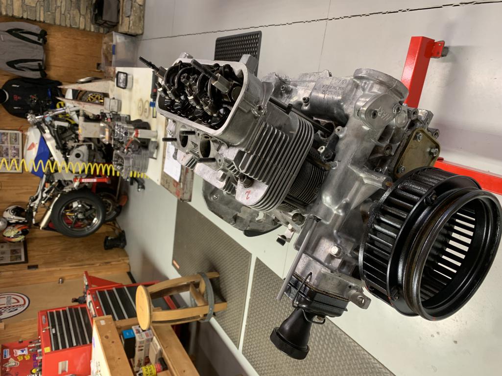 |
|
|
|
| sdoolin |
Feb 14 2025, 02:27 PM
Post
#20
|
|
Member Group: Members Posts: 414 Joined: 1-May 14 From: LouKY Member No.: 17,299 Region Association: None |
I'll likely button this engine up this weekend, and I'm looking for suggestions on how to verify oil pressure, before I install it back into the chassis. I am considering:
1) Adding oil and turning the engine by hand (no spark plugs) until I see oil at the oil filter mounting point just upstream of the oil pump. This seems like it'd be difficult at best (turning against the friction of the rings and all of the valve train), and maybe even impossible to really generate any oil pressure. 2) bolting on the transmission and using the starter to turn the engine until I see oil at the oil filter mounting point. I am very nervous about oil pressure as the only reason I'm doing this project is because I ran the engine (briefly) with low/no oil pressure and seized the rear most crank bearing. I never did determine with any confidence why there was low/no oil pressure. I suspect one or two things, but am mostly unsure. All actionable suggestions appreciated. |
|
|
|
|
2 User(s) are reading this topic (2 Guests and 0 Anonymous Users)
0 Members:

|
Lo-Fi Version | Time is now: 12th March 2025 - 05:00 AM |
Invision Power Board
v9.1.4 © 2025 IPS, Inc.